Building a Satellite Rotator
For the final two semesters of my degree, I’ve been assigned an open-topic design project. Students assemble into teams and either pick from a list of projects suggested by professors, or create their own ideas.
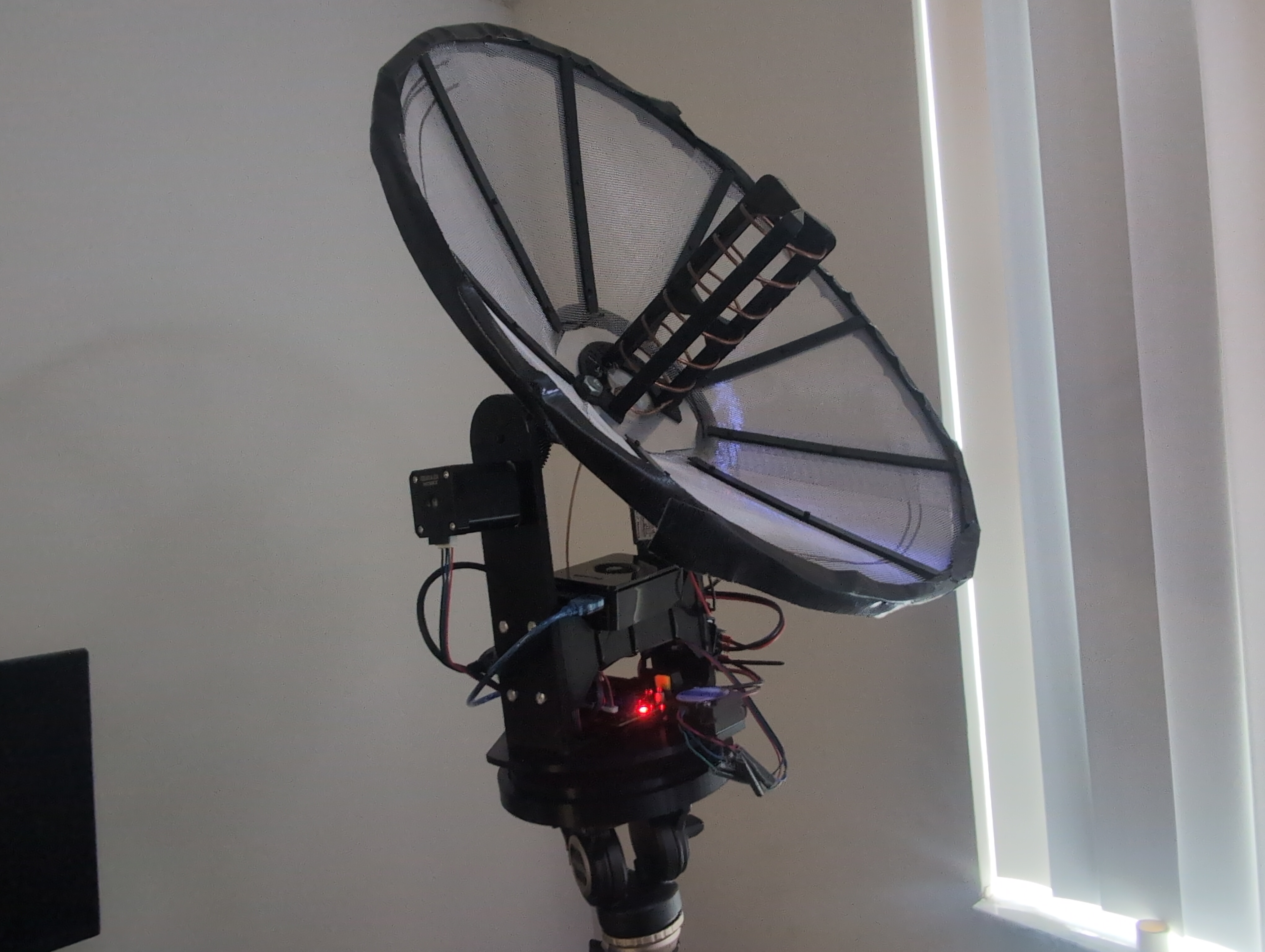
One of the projects that piqued my interest was a system for automated reception of weather satellite images using a 3D printed antenna.
I am a massive 3D printing enthusiast and a ham radio operator, so I felt this would be the perfect project for me. I convinced the rest of my team that this would be a lot of fun and we were luckily assigned to the project.
Our design philosophy was to create a low-cost solution which is available for students and hobbyists.
Responsibilities
We divided up responsibilities, and mine were as follows:
- Mechanical design and assembly of motion system and antenna
- Design of all electrical systems
- Firmware design
The rest of the team were to design the web interface, the database for storing received images and other information, and the connection to the decoding software.
Antenna Selection
For the antenna, I chose a 3D printed design from Thingiverse. This antenna was very lightweight and was centered on the frequency we wanted to use. I printed and assembled it, and after some preliminary tests it seems to work very well!
Mechanical Design
My idea for the mechanical system was to modify a pre-existing design for a camera pan/tilt system to accommodate the satellite antenna. I found a project I wanted to base my design around on Thingiverse. This project has some parts that make it a great jumping-off point:
Use of stepper motors
Steppers are great because they provide precise movement without any external measurement hardware and do not drift. They support a large payload and are very easy to drive. Best of all, I already have a bunch of them!Large weight capacity
Some quick torque math suggested that the design was strong enough. This is important because although our satellite antenna doesn’t weigh much more than a DSLR, the center of mass is not able to be centered in the way a camera could due to the size of the dish.Provided STEP files (!!!)
A lot of 3D printed designs publish only STL files. This makes them very annoying to modify in my experience. The process (at least in Autodesk Fusion, which is the modeling software I use) involves interpolating the STL mesh into an approximate Boundary Representation (BREP) which can then be edited. This “reverse engineered” BREP generally has a far higher complexity than the original model and causes my GPU (and me) to suffer immensely. STEP files are a BREP format right out of the box, so no interpolation is necessary.
Electrical and Software
The motor controller uses a repurposed 3D printer motherboard. This fits our goals in a few ways:
- Very low cost and available through many online sources
- Open source and thoroughly documented
- Equipped with microcontrollers (usually stm32f103s) which can be flashed through SWD
- Already available in my parts bin from old printer projects
For the radio, I used a Nooelec Smartee+. These are super cheap, and have a built-in bias tee (a component that lets us power accessories over coax). I’m using a Nooelec SAWbird GOES+ filter/amp, which combines a Surface Acoustic Wave filter (SAW) and a Low Noise Amplifier (LNA) into a single unit. As a backup radio, I have a Nooelec Smartee XTR, which has a larger tuning range but doesn’t have as clean of a signal.
The whole system is designed to be controlled by a Raspberry Pi. The Pi will run software that my teammates are currently designing which will:
- Take positioning data from an API (we are using N2YO.com)
- Send commands to the motor controller
- Take recordings from the SDR, pass them through decoding software, and present them to the user over a web interface
For power, we used a DeWalt 20v max platform drill battery. These batteries are powerful and have a decent capacity. I could save some money by building my own packs, but I think it’s not worth the potential fire risk (affordable battery spot welders are scary!). There are two buck converters which step the battery voltage down to 12v for the motors and 5v for the pi. Using socketed tool batteries allows for a long runtime, which makes testing much easier.
Current Status
As of writing this post:
- I am working on the motor firmware
- The hardware is effectively complete
- We may add a compass later for automatic heading detection, but we had issues with magnetic noise in the past
- The motor firmware is capable of seeking to positions provided over the serial interface, but the command parser is still buggy
Once the firmware is more polished, I want to go out into the field and do a test capture. Testing with a geostationary satellite is going to be good for practice, because we can still seek to the satellite given relative positions, but we don’t have to worry about timing the pass exactly right (you can never find parking during a pass!).
The rest of the team is hard at work on the backend software and the web interface. I’m super excited to see what the rest of the team has built, and I can’t wait to see the culmination of our efforts.